SQL Server Architecture (Explained)
⚡ Smart Summary
SQL Server Architecture follows a client-server model organized into three core layers: Protocol Layer for network communication, Relational Engine for query processing, and Storage Engine for data management and retrieval.
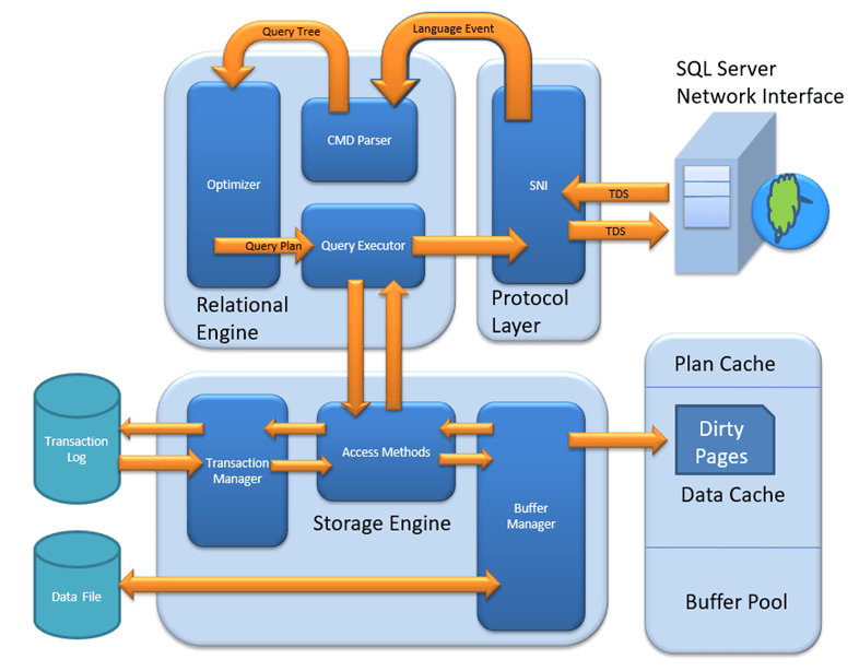
MS SQL Server is a client-server architecture. The MS SQL Server process starts with the client application sending a request. The SQL Server accepts, processes, and replies to the request with processed data. Let’s discuss in detail the entire architecture shown below:
As the below diagram depicts, there are three major components in SQL Server Architecture:
- Protocol Layer
- Relational Engine
- Storage Engine
Protocol Layer – SNI
The SQL Server Protocol Layer, also known as the Server Network Interface (SNI), supports three types of client-server architecture. Each protocol serves a different network scenario. Understanding these protocols is essential before exploring how queries are processed internally.
Shared Memory
Consider an early morning conversation scenario. Tom and his Mom are at the same logical place, their home. Tom asks for coffee and Mom serves it directly. Similarly, SQL Server provides the Shared Memory protocol when the client and server run on the same machine. Both communicate via shared memory without any network overhead.

Analogy: Tom maps to the Client, Mom maps to SQL Server, Home maps to the Machine, and verbal communication maps to the Shared Memory protocol.

Configuration notes: In SQL Management Studio, the “Server Name” option for a local connection can be “.”, “localhost”, “127.0.0.1”, or “Machine\Instance”.
TCP/IP
Now consider that Tom wants coffee from a shop located 10 km away. Tom is at home and the coffee shop is at a busy marketplace. They communicate via a cellular network. Similarly, SQL Server provides the TCP/IP protocol when the client and SQL Server are on separate machines connected over a network.

Analogy: Tom maps to the Client, the coffee shop maps to SQL Server, the home and marketplace map to remote locations, and the cellular network maps to the TCP/IP protocol.

Configuration notes: In SQL Management Studio, the “Server Name” option for a TCP/IP connection must be “Machine\Instance of the server.” SQL Server uses port 1433 by default for TCP/IP connections.
Named Pipes
Finally, Tom wants green tea from his neighbor Sierra. They are in the same physical location, being neighbors, and communicate via an intra-network. Similarly, SQL Server provides the Named Pipe protocol when the client and server are connected via a Local Area Network (LAN).

Analogy: Tom maps to the Client, Sierra maps to SQL Server, being neighbors maps to LAN, and the intra-network maps to the Named Pipe protocol.
Configuration notes: Named Pipes is disabled by default and must be enabled through SQL Configuration Manager.
What is TDS?
Now that the three types of client-server architecture are clear, here is a look at TDS:
- TDS stands for Tabular Data Stream.
- All three protocols use TDS packets.
- TDS is encapsulated in network packets, enabling data transfer from the client machine to the server machine.
- TDS was first developed by Sybase and is now owned by Microsoft.
The following table compares the three SQL Server connection protocols:
| Feature | Shared Memory | TCP/IP | Named Pipes |
|---|---|---|---|
| Network Scope | Same machine | Remote (WAN/Internet) | LAN only |
| Default Port | N/A | 1433 | 445 |
| Performance | Fastest (no network overhead) | Good (optimized for WAN) | Good (optimized for LAN) |
| Enabled by Default | Yes | Yes | No |
| Best Use Case | Local development and testing | Production remote access | Trusted LAN environments |
With the Protocol Layer handling network communication, the next step in SQL Server architecture is processing the query itself. This is where the Relational Engine takes over.
Relational Engine
The Relational Engine is also known as the Query Processor. It contains the SQL Server components that determine what a query needs to do and how it can be executed most efficiently. It is responsible for executing user queries by requesting data from the Storage Engine and processing the returned results.
As depicted in the architectural diagram, there are three major components of the Relational Engine:
CMD Parser
Data received from the Protocol Layer is passed to the Relational Engine. The CMD Parser is the first component to receive the query data. Its principal job is to check the query for syntactic and semantic errors and then generate a query tree.

Syntactic check: Like every other programming language, SQL Server has a predefined set of keywords and grammar rules. SELECT, INSERT, UPDATE, and many others belong to the predefined keyword list. The CMD Parser verifies that input follows these rules. If the user’s input deviates from the expected syntax, the parser returns an error.
Example: Consider a Russian walking into a Japanese restaurant and ordering in Russian. The waiter only understands Japanese and cannot process the order. Similarly, if a user types “SELECR” instead of “SELECT,” the CMD Parser returns an error because it does not recognize the keyword.
Semantic check: This is performed by the Normalizer. It checks whether the column names, table names, and other objects being queried actually exist in the schema. If they exist, the Normalizer binds them to the query. This process is also known as Binding. When user queries contain a VIEW, the Normalizer replaces it with the internally stored view definition.
Example: Running SELECT * from USER_ID would cause the parser to throw an error during the semantic check if the table USER_ID does not exist in the database.
Create Query Tree: This step generates different execution trees representing the various ways a query can be run. All trees produce the same desired output.
Optimizer
The Optimizer creates an execution plan for the user’s query. This plan determines how the query will be executed. Not all queries are optimized. Optimization applies to DML (Data Modification Language) commands like SELECT, INSERT, DELETE, and UPDATE. DDL commands like CREATE and ALTER are not optimized but are compiled into an internal form.

The query cost is calculated based on factors like CPU usage, memory usage, and input/output needs. The Optimizer’s role is to find the cheapest cost-effective execution plan, not necessarily the absolute best one.
Example: Imagine you want to open an online bank account. One bank takes a maximum of 2 days. You also have a list of 20 other banks that may or may not take less time. Searching all 20 banks may not find a faster option, and the search itself costs time. It would have been better to go with the first bank. Similarly, the SQL Optimizer uses exhaustive and heuristic algorithms to minimize query run time.
The Optimizer searches in three phases:
Phase 0: Search for Trivial Plan
This is the pre-optimization stage. For some queries, only one practical plan exists, known as a trivial plan. There is no need to search further because any additional searching would find the same execution plan at extra cost.
Phase 1: Search for Transaction Processing Plans
This includes searching for both simple and complex plans. The simple plan search uses statistical analysis of column and index data, typically restricted to one index per table. If no simple plan is found, a more complex search involving multiple indexes per table is performed.
Phase 2: Parallel Processing and Optimization
If the previous strategies do not produce an adequate plan, the Optimizer searches for parallel processing possibilities based on the machine’s processing capabilities. If parallel processing is not possible, a final optimization phase begins that uses all remaining options to find the best possible execution plan.
Query Executor
The Query Executor calls the Access Method in the Storage Engine. It provides an execution plan containing the data-fetching logic required for execution. Once data is received from the Storage Engine, the result is published to the Protocol Layer and sent to the end user.

After the Relational Engine determines how to execute a query, the Storage Engine handles the physical data operations. This layer manages how data is stored, cached, and retrieved from disk.
Storage Engine
The Storage Engine is responsible for storing data in a storage system like a disk or SAN and retrieving it when needed. Before examining Storage Engine components, it is important to understand how data is physically stored.

Data Files and Extents
Data files physically store data in the form of data pages, with each page having a size of 8KB. This is the smallest storage unit in SQL Server. Data pages are logically grouped into extents. No object is assigned an individual page directly; instead, maintenance is done via extents. Each page has a Page Header (96 bytes) carrying metadata such as page type, page number, used space, free space, and pointers to the next and previous pages.
File Types

Primary file: Every database contains one primary file. It stores all important data related to tables, views, triggers, and other objects. The extension is typically .mdf but can be any extension.
Secondary file: A database may or may not contain multiple secondary files. These are optional and contain user-specific data. The extension is typically .ndf but can be any extension.
Log file: Also known as Write-Ahead Logs. The extension is .ldf. Log files are used for transaction management, recovery from unwanted instances, and performing rollback of uncommitted transactions.
The Storage Engine has three main components. Each plays a specific role in managing data access and integrity.
Access Method
The Access Method acts as an interface between the Query Executor and the Buffer Manager or Transaction Logs. It does not perform execution itself but determines the type of query:
- If the query is a SELECT statement (DML), it is passed to the Buffer Manager for further processing.
- If the query is a Non-SELECT statement (DDL and DML), it is passed to the Transaction Manager. This mostly includes UPDATE, INSERT, and DELETE statements.

Buffer Manager
The Buffer Manager manages core functions for Plan Cache, data parsing, and dirty page handling.

Plan Cache
Existing query plan: The Buffer Manager checks whether the execution plan exists in the stored Plan Cache. If it does, the cached query plan and its associated data cache are used directly.
First-time cache plan: If a first-time query execution plan is complex, it is stored in the Plan Cache. This ensures faster availability the next time SQL Server receives the same query.
Data Parsing: Buffer Cache and Data Storage
The Buffer Manager provides access to the required data. Two approaches are possible depending on whether data exists in the cache:
Buffer Cache – Soft Parsing
The Buffer Manager looks for data in the Buffer Cache. If the data is present, the Query Executor uses it directly. This improves performance because fetching data from the cache requires fewer I/O operations compared to fetching from disk storage.

Data Storage – Hard Parsing
If data is not present in the Buffer Cache, the required data is searched in data storage on disk. The data is then also stored in the data cache for future use.

Transaction Manager
The Transaction Manager is invoked when the Access Method determines that a query is a non-SELECT statement. It ensures data consistency and durability through several sub-components:

Log Manager
The Log Manager keeps track of all updates performed in the system through logs stored in Transaction Logs. Each log entry contains a Log Sequence Number along with the Transaction ID and Data Modification Record. This mechanism tracks committed and rolled-back transactions.
Lock Manager
During a transaction, the associated data in storage enters a locked state. The Lock Manager handles this process, ensuring data consistency and isolation. These properties are also known as ACID (Atomicity, Consistency, Isolation, Durability).
Execution Process
The execution process follows these steps:
- The Log Manager starts logging and the Lock Manager locks the associated data.
- A copy of the data is maintained in the Buffer Cache.
- A copy of data to be updated is maintained in the Log Buffer, and all events update data in the Data Buffer.
- Pages that store modified data are known as Dirty Pages.
Checkpoint and Write-Ahead Logging
The checkpoint process runs approximately once per minute and marks all dirty pages for writing to disk. However, the page is first pushed to the data page of the log file from the Buffer Log. This mechanism is known as Write-Ahead Logging. The dirty pages remain in the cache even after being written to disk.
Lazy Writer
When SQL Server observes a heavy load and buffer memory is needed for new transactions, it frees dirty pages from the cache. The Lazy Writer operates on the LRU (Least Recently Used) algorithm to clean pages from the buffer pool to disk.
How SQL Server Processes a Query End-to-End
Understanding each layer individually is valuable, but seeing how they work together clarifies the complete picture. When a client application sends a SQL query, the following sequence occurs:
The Protocol Layer receives the request via Shared Memory, TCP/IP, or Named Pipes and wraps it in a TDS packet. The Relational Engine then takes over: the CMD Parser checks syntax and semantics, the Optimizer generates the cheapest execution plan, and the Query Executor begins data retrieval.
The Query Executor calls the Storage Engine’s Access Method, which routes SELECT queries to the Buffer Manager and modification queries to the Transaction Manager. The Buffer Manager checks Plan Cache and Buffer Cache first (soft parsing). If data is not cached, it performs a disk read (hard parsing). For write operations, the Transaction Manager coordinates Log Manager, Lock Manager, and the checkpoint process to ensure ACID compliance.
Once the Storage Engine returns the requested data, the Relational Engine formats the result set, and the Protocol Layer delivers it back to the client application through the same TDS protocol.
How to Choose the Right Protocol for SQL Server Connections
Selecting the correct protocol depends on the physical relationship between the client and the server, as well as performance requirements.
Use Shared Memory when the client application runs on the same machine as SQL Server. This is the fastest option because it eliminates all network overhead. It is ideal for local development, testing, and single-machine deployments.
Use TCP/IP when the client and server are on different machines connected over a WAN or the internet. This is the most commonly used protocol in production environments. SQL Server listens on port 1433 by default, and this protocol supports encrypted connections via TLS.
Use Named Pipes when the client and server are on the same trusted LAN and performance on internal networks is a priority. Named Pipes is disabled by default and must be enabled through SQL Server Configuration Manager. It is less common in modern deployments but remains useful for legacy intranet applications.