
Mapping in Informatica: Create, Components & Parameters
 Editorial Team
⚡ Smart Summary
Mapping in Informatica is the object that links source definitions to target definitions through transformations, defining exactly how each column of data is read, changed and loaded during an ETL session run.
What is a Mapping?
A mapping is a collection of source and target objects linked together by a set of transformations. These transformations consist of a set of rules, which define the data flow and how the data is loaded into the targets.
A mapping consists of the following set of objects:
- Source Definition – a source definition defines the structure and characteristics of the source, its underlying data types, the type of the data source, and so on.
- Transformation – transformation objects define how the source data is transformed, and various functions can be applied during the process.
- Target Definition – the target definition defines the final target where the data will be loaded.
- Links – links connect the source definition to different transformations and target tables. They define how the data flows from source to target and through the transformations.
Why do you need Mapping?
A mapping is an object in Informatica with the help of which you can define how the source data is modified before it reaches the destination or target object. For example, if you have an employee name stored as “Bill Clinton” in your source system and the target system requires the employee name in the format “Clinton Bill”, such operations can be designed at the mapping level. In basic terms, what you do with the source data is defined at the mapping level.
A mapping is the basic Informatica object with the help of which we can define the data transformation details and source/target object characteristics. Mappings help us to define the data transformation at the individual column level for each row. Even in a single mapping you can handle multiple sources and targets.
Components of Mapping
The basic components of a mapping are:
- Source tables
- Mapping parameters and variables
- Target objects
- Mapping transformations
There are various objects that constitute a mapping. A mapping can consist of sources, targets, mapping parameters and variables, mapplets, various transformations, and user-defined functions.
- Mapping Source: mapping sources are the objects from where you fetch the source data. A source can be a database table, a flat file, an XML source or a COBOL file source.
- Mapping Target: the mapping target is the destination object where the final processed data gets loaded. A mapping target can be a relational table of a database, a flat file or an XML file. Sources and targets are mandatory in any mapping, although their type can differ.
- Mapping Parameters and Variables: mapping parameters and variables help you create temporary variable objects that let you define and store temporary values while the mapping processes data. Mapping parameters and variables are optional, user-defined data types which can be created for a mapping and can be referenced and updated for a specific requirement. We will learn more about mapping parameters and variables in this section.
- Mapplets: mapplets are objects which consist of a set of transformations, sources or targets. Mapplets are generally created to reuse the existing functionality of a set of transformations. A mapplet can be used in any number of mappings.
What is Stage Mapping?
A stage mapping is a mapping in which we create a replica of the source table. For example, in a production system, if you have an “employee” table then you can create an identical table “employee_stage” in the ETL schema.
Having a local stage table offers various advantages. Production downtime will not affect your ETL system, because you have your own “employee_stage” table instead of referring to the production “employee” table. In a production system, there can be other operations and processes which affect performance. However, when you have a replica staging table, only ETL processes will access it. This offers performance benefits.
In stage mappings,
- Source and target tables have identical structures
- The data in the target table is a replica of the source table data, or
- Data in the stage (target) table is a subset of the source data.
For example, if your source table contains employee details of deptno 10, 20, 30, and 40, the staging table can be a table having employee records of deptno 10 & 30 only.
Stage tables in a data warehouse make data transformation efficient by fetching only the data relevant to us, and minimize the dependency of the ETL/data warehouse on the real-time operational system.
How to Create a Mapping
In this exercise, we will create a stage mapping, in which the source will be the “emp” table and the target will be “emp_target”. The mapping is built in the workspace shown below.

Naming convention – mapping names are prefixed with ‘m_’ followed by the source and target table names separated by an underscore sign.
Example – if you are loading the emp_target table from the emp table, then the mapping name can be ‘m_emp_emp_target’.
Step 1) Launch Mapping Designer.
- Open the Informatica Designer tool
- Click on the Mapping Designer icon to launch Mapping Designer
The icon sits on the Designer toolbar, as shown below.

Step 2) In Mapping Designer:
- Click on the Mappings menu
- Select the Create option
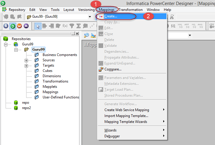
Step 3) Enter the mapping name as ‘m_emp_emp_target’ and select the OK button.

The mapping will be created and listed under the Mappings folder in the repository navigator.

A mapping must have at least a source and a target, so you will now add both.
Step 4) In this step we will:
- Select the “emp” source table under the Sources folder.
- Drag and drop the “emp” table into Mapping Designer.

In Mapping Designer, the imported source table is shown with its source qualifier.

Note – when you import any relational (database) table into a mapping, an additional object of source qualifier type will also be created. This source qualifier transformation is necessary and helps the Informatica Integration Service identify the source database table and its properties. Whenever you import a source table, a source qualifier transformation will also be created. You should never delete a source qualifier object in a mapping.
Step 5) In this step we will:
- Select the “emp_target” target table under the Targets folder.
- Drag and drop the “emp_target” table into Mapping Designer.

In Mapping Designer, the “target table” will be imported and shown.

To manage the view space, you can iconize these objects in the mapping.
Step 6) Right-click anywhere in the empty Mapping Designer workspace and select the option – Arrange all Iconic.

After selecting the option “Arrange all Iconic”, the workspace will look like this.

Step 7) In Informatica, we design with the flow running from left to right. So source tables should be on the left side, and target tables should be on the right. To arrange the tables in our workspace, select the “emp_target” table, then drag and drop it to the right side of the emp table.

After this rearrangement, the workspace will look like this.

Note – periodically use the “Ctrl+S” shortcut to save changes to the repository.
Step 8) Now you have source and target tables in your mapping, but the mapping is not yet complete. The source and target tables should be linked to complete a mapping. To link the source and targets, double-click on the SQ_EMP and EMP_TARGET objects to change their view from iconic to graphic.
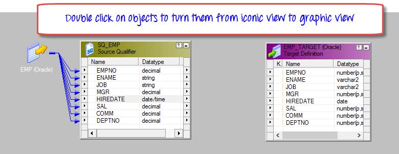
Step 9) Right-click on the Mapping Designer workspace and select the “Autolink” by name option.

Step 10) To link the source with the target table:
- Select the source table columns.
- Drag and drop the columns onto the target table.

The source and the target tables will be linked, and connecting arrows will appear from the source to the target table.

Note – here you have linked all source columns to the respective target table columns. It means that for every source record fetched, all the columns of the target will get loaded. If you want to exclude any specific column from getting loaded, click on that column link and press the delete key on the keyboard. The link will get removed, and the target column will not get loaded.
Step 11) Use the shortcut “Ctrl+S” to save changes to your mapping. In the output window, you can see the message of mapping validation/parsing. It confirms that your mapping is valid. Also, there will be a temporary green tick mark next to the mapping name in the mapping folder tree, indicating the mapping is done successfully.

In mappings there can be a requirement where we need to pass a variable to the mapping, or there can be a scenario where we need to calculate temporary values and store them for the next session run of the mapping. For these purposes, we create mapping parameters and variables.
Mapping Parameters and Variables
Like every programming language, Informatica has its own way of defining parameters and variables. But unlike other programming languages, Informatica is not a code-based language. To create parameters and variables in Informatica, you have to follow the predefined syntax and navigation.
Difference between parameters and variables –
| Mapping Parameters | Mapping Variables |
|---|---|
| Mapping parameters are those data types whose value, once assigned, remains constant throughout the mapping run. If you have created a mapping parameter deptno=20, then the value 20 will be constant for the whole mapping run. Wherever the parameter is referenced, it will always return the value 20 for that instance of the mapping run. For a new mapping instance, the parameter value can be redefined. | Mapping variables are objects which can be referenced throughout the mapping run (to access their values) and their values can be reassigned. For example, a mapping variable total_salary can be used in a mapping, and its value can be updated based on salaries. |
| Changed between runs by editing the parameter file. | Saved to the repository after a successful session run and reused as the start value of the next run. |
The mapping parameters and variables are specific to a mapping only. They cannot be referenced in another mapping.
How to Create Mapping Parameter
When you create a mapping parameter, during execution of the mapping the Integration Service looks for its assigned value. These values can be assigned in the following places.
- Inside a parameter file
- In pre-session variable assignment
- Initial value in the repository
- Default value assigned during variable creation
Step 1) To create a mapping parameter, in Mapping Designer:
- Select the Mappings menu
- Select the Parameters and Variables menu

Step 2) In the next screen:
- Click on the add new variable menu
- From the drop-down, select the type as parameter
- Enter the parameter name as $$Deptno
- Enter an initial value of 10
- Select the OK button

Now you have created a mapping parameter deptno with an initially assigned value of 10, and this parameter can be referenced inside the mapping.
How to Create Mapping Variable
Step 1) In Mapping Designer:
- Select the Mappings menu
- Select the Parameters and Variables menu

Step 2) On the next screen:
- Click on the add new variable menu
- From the drop-down, select the type as variable
- Enter the variable name as $$TotalSalary
- Select DataType as decimal
- Enter an initial value of 0
- Select the OK button

This will create a mapping variable. Variable functions such as SetVariable and SetMaxVariable change its value during the run.
Note – mapping parameter and variable names always begin with $$.
