OSI Model Layers and Protocols in Computer Network
⚡ Smart Summary
OSI Model Layers and Protocols define how network communication is conceptually structured into seven layers — Physical, Data Link, Network, Transport, Session, Presentation, and Application. Each layer owns specific responsibilities and protocols and serves only the layer above and below it.
What is the OSI Model?
The OSI (Open Systems Interconnection) Model is a conceptual reference model that describes how data moves between systems on a network. It divides communication into seven abstract layers, each with a clearly defined responsibility and a specific set of protocols. The model is not implemented exactly as drawn on real networks — TCP/IP is the protocol stack actually deployed — but the OSI layers remain the standard vocabulary engineers use to reason about network problems.
Characteristics of the OSI Model
- A layer is created only where a distinct level of abstraction is needed.
- Each layer’s function is chosen so it aligns with an internationally standardised protocol.
- Layers should be numerous enough to separate concerns but few enough to avoid runaway complexity.
- Each layer relies on the layer immediately below it for primitive services and exposes services to the layer immediately above.
- A change inside one layer should not require changes in the layers above or below it.
Why Use the OSI Model?
- Provides a shared vocabulary for understanding communication across a network.
- Makes troubleshooting easier by separating functions into independent network layers.
- Helps engineers absorb new technologies by mapping them onto familiar layers.
- Lets you compare functional relationships across different protocol stacks.
History of the OSI Model
- Late 1970s — the ISO began a programme to define general networking standards.
- 1973 — an experimental packet-switched system in the UK highlighted the need for higher-level protocols.
- 1983 — the OSI model was first published as a detailed interface specification.
- 1984 — ISO formally adopted the OSI architecture as an international standard (ISO 7498).
The 7 Layers of the OSI Model
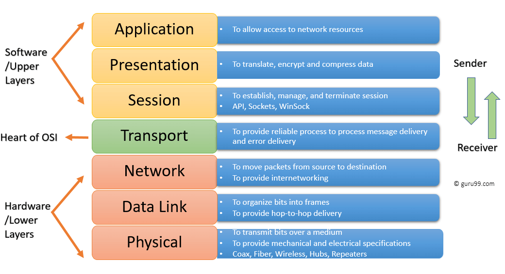
The OSI Model is a layered reference architecture in which each layer performs a specific function. The seven layers work together to deliver data from sender to receiver.
- Upper layers (Application, Presentation, Session): deal with application semantics and run primarily in software.
- Lower layers (Transport, Network, Data Link, Physical): deal with data transport, packetisation, framing, and the physical medium. Data Link and Physical also include hardware.
The seven layers, top to bottom, are:
- Application
- Presentation
- Session
- Transport
- Network
- Data Link
- Physical
Network layers diagram.
Physical Layer
The Physical layer defines the electrical, mechanical, and physical specifications of the data connection. It carries raw bits over a transmission medium and is unconcerned with protocols or higher-layer semantics. PRI (Primary Rate Interface) is one telecommunications example that operates at this layer — learn more in the PRI tutorial.
Examples of Physical-layer hardware include network adapters, Ethernet cabling, repeaters, and networking hubs.
Data Link Layer
The Data Link layer detects and corrects errors that can occur on the Physical layer and manages the protocol that establishes and terminates a link between two directly connected devices. It frames raw bits into structured frames and handles physical (MAC) addressing.
Data Link is split into two sublayers:
- Media Access Control (MAC): controls how devices gain access to the shared medium and how they transmit data.
- Logical Link Control (LLC): identifies and encapsulates network-layer protocols and detects errors.
Important functions of the Data Link layer
- Framing: splits Network-layer data into frames.
- Adds a header containing the physical (MAC) address of source and destination.
- Provides hop-to-hop delivery of frames between adjacent devices.
- Detects errors and re-requests damaged or lost frames.
- Offers a mechanism to traverse independent networks that are linked together.
Network Layer
The Network layer provides the functional and procedural means of transferring variable-length data sequences between hosts located on different networks. It handles logical addressing (IP), routing, and packet forwarding.
Network-layer delivery is not inherently reliable — that guarantee is the Transport layer’s job. Layer-management protocols at this layer include:
- Routing protocols (OSPF, BGP, RIP).
- Multicast group management (IGMP).
- Network-layer address assignment (DHCP).
Transport Layer
The Transport layer builds on the Network layer to provide end-to-end data transport between processes on source and destination machines. It maintains quality-of-service properties such as ordering, reliability, and flow control.
The Transport layer divides upper-layer messages into segments, numbers them, and reassembles them at the receiver. It guarantees error-free, in-sequence delivery when used with reliable protocols like TCP, or accepts loss in exchange for speed when used with UDP.
Important functions of the Transport layer
- Segments the message received from the Session layer and numbers each segment.
- Delivers each segment to the correct process on the destination machine using ports.
- Ensures the entire message arrives without error, retransmitting when necessary.
- Manages flow control so a fast sender does not overwhelm a slow receiver.
Session Layer
The Session layer controls the dialogues (sessions) between two computers. It establishes, manages, and terminates logical connections, handles authentication where required, and supports both full-duplex and half-duplex dialogues. It is most often implemented in environments that use remote procedure calls.
Important functions of the Session layer
- Establishes, maintains, and ends a session between two systems.
- Enables both systems to enter into a controlled dialogue.
- Adds checkpoints to a data stream so a session can resume after an interruption.
Presentation Layer
The Presentation layer defines the format in which data is exchanged between two communicating entities and handles compression and encryption. It is sometimes called the syntax layer.
Functions of the Presentation layer
- Character-set translation (for example, ASCII to EBCDIC).
- Data compression to reduce bits on the wire.
- Data encryption — for example, TLS to protect payload integrity and confidentiality.
- Provides format support for services such as email and file transfer.
Application Layer
The Application layer is the layer closest to the end user and the only one that interacts directly with applications. It does not contain the applications themselves — instead it exposes the network services that applications use.
Functions of the Application layer
- Identifies communication partners, determines resource availability, and synchronises communication.
- Lets users log on to a remote host.
- Provides email services and directory access.
- Offers distributed-database access for global information about objects and services.
Interaction Between OSI Model Layers
Information sent from one computer application to another flows down through the OSI layers on the sender, across the wire, and back up through the layers on the receiver.
- Each layer communicates with the layer above it, the layer below it, and the corresponding peer layer on the remote system.
- In the diagram below, the Data Link layer of the first system communicates with the Network and Physical layers on the same host and with the Data Link layer of the remote system.

Protocols Supported at Each OSI Layer
| Layer | Name | Common Protocols |
|---|---|---|
| Layer 7 | Application | SMTP, HTTP, HTTPS, FTP, POP3, SNMP, DNS |
| Layer 6 | Presentation | MPEG, ASCII, SSL, TLS |
| Layer 5 | Session | NetBIOS, SAP, RPC |
| Layer 4 | Transport | TCP, UDP, SCTP |
| Layer 3 | Network | IPv4, IPv6, ICMP, IPsec, ARP, MPLS |
| Layer 2 | Data Link | Ethernet, PPP, Frame Relay, ATM, HDLC |
| Layer 1 | Physical | RS-232, 100BaseTX, ISDN, IEEE 802.11 (physical signalling) |
Differences Between OSI and TCP/IP

| OSI Model | TCP/IP Model |
|---|---|
| Provides a clear distinction between interfaces, services, and protocols. | Does not draw a strict line between services, interfaces, and protocols. |
| Has seven layers. | Has four layers (Application, Transport, Internet, Network Access). |
| Uses a dedicated Network layer for routing. | Uses a single Internet layer that combines routing and addressing. |
| Has separate Physical and Data Link layers. | Combines the Physical and Data Link layers into one Network Access layer. |
| Transport layer is connection-oriented. | The TCP/IP Transport layer is both connection-oriented (TCP) and connectionless (UDP). |
| Minimum OSI header size is around 5 bytes. | Minimum TCP/IP header size is 20 bytes. |
Advantages of the OSI Model
- Standardises routers, switches, and other hardware around well-defined layer boundaries.
- Reduces complexity and standardises interfaces.
- Facilitates modular engineering — vendors can innovate inside one layer without breaking others.
- Guarantees interoperable technology across vendors.
- Accelerates the evolution of network protocols.
- Provides support for both connection-oriented and connectionless services.
- Remains the standard reference model in computer networking education.
- Offers flexibility to adapt to many types of protocols.
Disadvantages of the OSI Model
- Fitting real-world protocols into OSI layers can be tedious.
- It is a reference model only — it does not define specific protocols.
- Some services are duplicated across layers (for example, error checking at Transport and Data Link).
- Layers cannot run in parallel — each one waits for the previous layer’s output.