
Router Transformation in Informatica: Multiple Conditions Example
 Editorial Team
⚡ Smart Summary
Router transformation in Informatica is an active, connected object that tests incoming rows against several group filter conditions at once and sends each row to the matching output group, or to the default group.
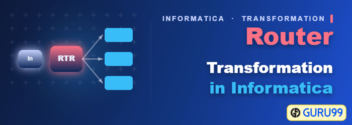
What is Router Transformation?
Router transformation is an active and connected transformation which is similar to Filter transformation, used to filter the source data.
The additional functionality provided beside filtering is that the discarded data (filtered out data) can also be collected in the mapping, as well as the multiple filter conditions can be applied to get multiple sets of data.
For example, when filtering the data for deptno = 10, we can also get those records where deptno is not equal to 10. So, Router transformation gives multiple output groups, and each output group can have its own filter condition.
In addition there is also a default group. This default group has those record sets which do not satisfy any of the group conditions. For example, if you have created two groups for the filter conditions deptno=10 and deptno=20 respectively, then those records which are not having deptno 10 and 20 will be passed into this default group.
In short, the data which is rejected by the filter groups will be collected by this default group, and sometimes there can be a requirement to store this rejected data. In such scenarios, the default output group can be useful.
To allow multiple filter conditions, the Router transformation provides the group option.
- There is a default input group which takes input data.
- There is also a default output group which provides all those data which is not passed by any filter condition.
- For every filter condition, an output group is created in Router transformation. You can connect different targets to these different groups.
Components of Router Transformation
Before building the mapping, it helps to know the four parts the Designer creates for you. A Router transformation is made up of one input group, a set of output groups, the ports inside them, and the conditions that decide where each row goes.
| Component | What it does |
|---|---|
| Input group | The single entry point for the transformation. Every incoming row arrives here once, no matter how many output groups exist. |
| User-defined output group | A group you create and name yourself, such as deptno_20. Each one carries its own group filter condition. |
| Default output group | Created automatically as soon as the first user-defined group exists. It has no filter condition and cannot be edited or deleted. |
| Group filter condition | A boolean expression written in the Expression Editor. Rows for which it evaluates to TRUE leave through that group. |
The Designer copies the port definitions from the input group into every output group, so the ports do not have to be recreated group by group. Two rules follow from this design:
- Rows can be duplicated. If a row satisfies more than one group filter condition, it is passed once to each group that matches. This is the usual reason a target ends up with more rows than the source.
- Rows can be dropped. If the default group is left unconnected, the rows that reach it simply disappear from the pipeline, which is the quickest way to discard unwanted data.
Router Transformation vs Filter Transformation
Both objects test data against a condition, and both are active transformations, so the choice between them comes down to how many conditions are involved and whether the rejected rows matter.
| Point of comparison | Filter transformation | Router transformation |
|---|---|---|
| Conditions per object | One | One or many, each in its own group |
| Rejected rows | Dropped and unavailable | Collected in the default group |
| Output groups | A single output pipeline | One pipeline per group, plus the default group |
| Source reads | One read per Filter when conditions are chained | One read for all conditions |
| Typical use | Removing rows that are never needed | Splitting one source into several targets |
Testing three conditions with Filter transformations means three objects, and in a chained design the same source rows are evaluated repeatedly. One Router does the same work in a single pass, which is why it is generally the more efficient option once a second condition appears. For a single throwaway condition, the simpler Filter transformation is still the better fit.
How to Create a Router Transformation in Informatica
The walkthrough below builds a Router that sends department 20 employees to a target table. Follow the nine steps in order in the Mapping Designer.
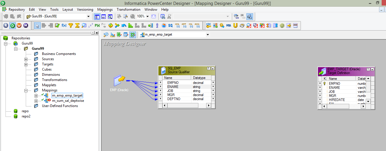
Step 1) Create a mapping having source “EMP” and target “EMP_TARGET.” The Mapping Designer canvas then holds the source definition, its Source Qualifier and the target definition, as shown below.
Step 2) Then in the mapping
- Select Transformation menu
- Select create option
The menu path used to start the wizard is highlighted in the next screenshot.

Step 3) In the create transformation window
- Select router transformation
- Enter a name for the transformation “rtr_deptno_10”
- Select Create option
Step 4) The Router transformation will be created in the mapping. Select the done option in the window. The Create Transformation window used across both steps is shown below.

Step 5) Drag and drop all the columns from Source Qualifier to Router transformation. Every port is now linked into the new object, as the screenshot shows.

Step 6) Double click on the Router transformation, then in the transformation property of it
- Select group tab
- Enter group name “deptno_20”
- Click on the group filter condition
The Groups tab with the new group added is shown next.

Step 7) In the Expression Editor, enter filter condition deptno=20 and select the OK button. The editor holding this condition is shown below.

Step 8) Select the OK button in the group window. The condition now appears against the group, as the next screenshot shows.

Step 9) Connect the ports from the group deptno_20 of Router transformation to target table ports. The finished mapping runs from the source through the group to EMP_TARGET.
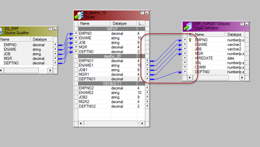
Now, when you execute this mapping, the filtered records will get loaded into the target table.
Router Transformation Best Practices and Common Errors
The mapping above uses one group, which hides most of the behaviour that causes support tickets later. The points below cover what changes once a second group appears.
- Watch for duplicated rows. Group conditions are not mutually exclusive. Writing sal>1000 in one group and deptno=20 in another means an employee who matches both is loaded twice. Make the conditions exclusive, or accept the duplication deliberately.
- Connect the default group when rejects matter. Rows that satisfy no condition are lost unless the default group is wired to a target or a reject file. Auditable loads usually keep them.
- Name groups after the rule, not the target. The example group deptno_20 reads clearly; a group called group1 does not. Note that the transformation itself is named rtr_deptno_10 in this walkthrough while the group filters on deptno 20, which is exactly the kind of mismatch a naming standard prevents.
- Filter before you route where you can. Rows that no group will ever want are cheaper to remove in the Source Qualifier query than to carry into the Router.
- Do not treat Router as a join. It splits one pipeline into several. Bringing the branches back together needs a Union transformation, and combining two different sources needs the Joiner transformation.
A group whose condition returns NULL rather than TRUE or FALSE is treated as not matching, so rows with null values in the tested column fall through to the default group. Handling nulls explicitly in the condition avoids that surprise during performance tuning and testing.
