Business Process Testing(BPT) Framework in QTP/UFT
What is Business Process Testing?
Business Process Testing(BPT) is a process that aligns software testing processes with business goals in order to reduce complexity, time consumption and efforts in a testing lifecycle. Business process testing is an end to end testing that helps to check the readiness of the software application from the business as well as customer’s perspective.
BPT Framework
BPT(Business Process Testing) Framework is an inbuilt micro focused automation framework used with the Quality Center. BPT helps to indulge Business Analysts or SMEs in the automation process. They can also design the automation scenarios and execute them as per their requirements without having prior automation or coding knowledge.
The following are the building blocks of the BPT Framework
- Components
- Application Area
- Flows
- Business Process Test
Component: (is also called Business Component) is a reusable set of automation statements that performs a particular predefined task in AUT. It is similar to VBScript function and QTP action but designed to use in BPT framework.
Application Area: It is a repository, containing all the resources, required to develop the Business Components. Resources include a shared object repository; reusable functional libraries…etc. It is a logical entity, which you cannot see the physical existence in a file system.
Business Process Test: A scenario comprising a serial flow of Business Components, designed to test a specific Business process of an application.
Flow: At times, you need to use the similar Components in the same order in multiple BPTs. Instead of adding the same Components in each and every BPT, you can create a Flow of Business Components. The Flow can be called directly instead of calling each Component separately.
Why BPT?
There are some challenges with traditional automation mentioned below:
- Lack of co-ordination between manual testers / Subject matter experts and automation testers.
- There is no role for the manual testers in the automation process.
- Lack of standards in automation development.
- There is a chance of huge maintenance effort without an intelligent framework.
- Usually, automation tester does not have good application knowledge, and he tends to the develop inefficient scripts
BPT overcomes the above challenges with a standardized framework where it involves the SME’s / Manual testers as a part of automation development and defines a standard process of developing BPTs.
Manual testers design the manual Component for the required functionality, which is automated by the automation tester. Manual / Automation testers will arrange those automated Components in a sequence to form the BPT, which becomes a test scenario.
BPT defines different roles, performed by various resources. BPT helps with optimization in the utilization of the resources and their expertise. Roles in BPT are classified as follows:
- SME
- QTP Expert
- Tester
SME: SME’s is a Business Analyst or the manual tester who has good knowledge of the application. They design the manual Business Components which will test a specific action or functionality. While designing the manual Business Components, they will clearly mention the test steps and the expected results.
QTP Expert: QTP Experts convert the manual Business Component into automated Component by automating the steps mentioned in the manual Component.
Once the Components are designed, an SME, or QTP Expert will arrange those Components to form BPT, which forms a test scenario.
Tester: Tester can be a manual tester or QTP expert who can execute the BPT’s from quality center.
Getting Started with BPT
Software requirements:
- QTP/UFT (“QTP Latest version“) Valid License.
- You should have QC / ALM (QC Latest version) access with Business Components Module, which won’t come along with QC. You need to buy a separate license for it.
Software configurations:
- QTP: Enable the option ‘Allow other HP products to run tests and Components’
- QC: Following add-ins should be installed.
- QC Connectivity Add-in
- QTP Add-in
Implementation of BPT Framework:
As it is an inbuilt framework, you do not need to write code to build the framework. You just need to prepare the required artifacts that are building the building blocks of BPT.
Lets briefly study important Modules in Quality Center (HP ALM)
Business Components Module: Enables us to create, manage, and automate reusable Business Components, which will contain the steps to perform a specific function in a Business process. Components are typically classified as follows-
- Manual Components
- Automated Components
- Keyword-Driven Components
- Scripted Components
Test Plan module: This is the module where you drag and drop the Components in some logical order to prepare BPT’s which will forms one test scenario, and you can debug the Components.
Test Lab module: Enables us to execute the Business process tests and view the results. Even you can run the BPT’s parallel in the different machines using this module.
The typical BPT automation process involves the following stages.
- Creating the Manual Components
- Automating the Components
- Developing the Flow’s or BPT’s
- Debugging the BPT’s
- Executing the BPT’s
Step 1) Creating the Manual Components
Login into QC

Navigate to Business Components module.
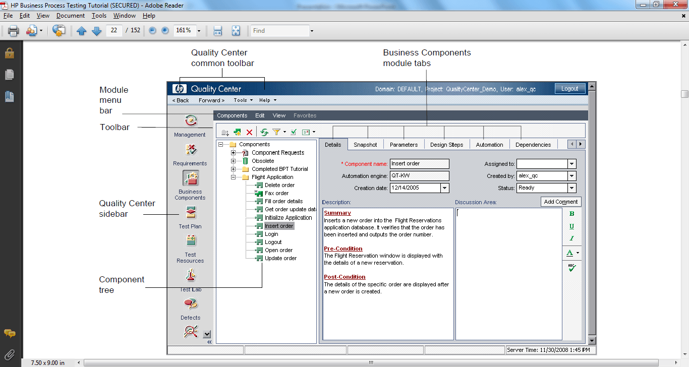
Business Components and folders are identified by specific icons in the Component tree mentioned below-

Folder: used to classify your Components in the logical segregation.

Component Request Folder: Manual testers or SME’s place their Components which they want to get it automated.

Obsolete Folder: You can move all the invalid Components to this folder, so that you can review before removing them permanently from QC.

Component: This is the symbol is used to represent Component. Manual Business Components are represented by an M symbol on the Component icon. As shown below.

A Component can be any one of the following status in given time, which is Under Development, Ready, Maintenance and Error status respectively.


When a Component request is initiated in the Test Plan module then it is in the ‘Not Implemented’ status (shown below). When this particular Component is moved from request folder to the Component folder it is changed to ‘Under development’ status.

Toolbar in the Business Component module

Create the new manual Business component.
Create the new folder so that you can create all your application related Components in one place.
Select the Components folder -> Click on the New Folder

Enter the some meaning full name to represent your application and click on ok. You can even create subfolders under your main folder.
Selected folder in which you want create Component -> click on the ‘New Component’ button

Enter a Component name the resembles the action it is going to perform making it easy to choose the Components while preparing the BPT’s. Click on ok button.
A new Component is created and on the right side.
Lets study the various tabs on the component
I. Details Tab: It contains some basic fields like Component name, created by, creation date… etc.
The Description tab, has three sections Summary, Pre-condition and Post-condition.
In the summary section, you can mention the brief description of the Component functionality and its outcome.
In the Pre-Condition section, mention application status that is required to use this Component.
In the Post-Condition section, mention the application status after performing the Component steps.
Do keep in mind Pre and Post conditions while creating a logical sequence of the Components to create the BPT.
In the Discussion area, you can add comments related to Component.

II. Snapshot Tab: You can use this tab to capture a snapshot of the particular page, to which the Component belongs.
III. Parameters Tab: You can use this tab if you want to pass data or retrieve data from the Component. These are similar to action/test parameters in QTP.
Click on the New link to add the new parameter, you need to provide the
- Parameter Name: Name of the Parameter.
- Value Type: Type of the parameter (Number, Date, String, Password…etc.).
- Default value: You could enter some default value which can be used if you didn’t pass any value from the Component.
- Description: You can mention a brief description of the parameter.

Output parameters can be added or deleted similar to input parameters. If you want to return any value(s) from the Component, then you have to use output parameters.
IV. Design Step Tab: Contains the steps which Component has to perform. Buttons in the design tab are displayed in the following order.
Add New Step, Edit, Delete, Copy, Paste, Create/Select Parameter, Complete Parameter, Search, RowHeight, Save and Automate

To add the step click on ‘Add New Step’, the Component step editor is opened. Enter the step name to describe the step, description (exact operation that you want to perform on the application) and the expected result (application status after performing the step).
Step editor is also opened when you select a step and click on the edit step button.
You have the text editor toolbar in the step editor, which you can use to format the strings like bold, italic and underline.

V. Automation Tab: Will displays the automation steps related to the Component, if the Component is already automated. You will discuss in detail about this step in the next step ‘Automating the Manual Component’
VI. Dependencies Tab: Will display the dependency relationships that exist betyouen other entities like Components, BPTs, flows, test resources, and application areas. Dependencies tab contains following three tabs
Resources tab show the application areas (logical grouping/name of the all resources required to automate the Component) used by the Component.
Used By tab will displays the details of BPTS and flows that include the currently selected Component. If you want to navigate to the particular BPT or Flow you can just click the test or flow name, you is navigated to the BPT or Flow in Test Plan module.
Application Area tab displays the name of the application area used by the Component, as youll as Used By and Using grids, which display the entities that use the application area, and the resources that the application area uses.
VII. History tab: Displays changes made to any fields in an entity. For each change, it will display the time stamp of the change and the user name that made the change. History tab contain two sub tabs:
Audit Log tab displays a list of changes made to different fields, time stamp and user details.
Business tab displays the different versions of the selected Component.
Step 2) Automating the Manual Components
Building the Application Area
Application Area is a logical entity which helps us to group the all required resources to automate the application or part of application. Application area contains shared object repositories, function libraries and all other settings required to automate the Components.
You can create one application area for the whole application or as many as application areas for the different parts of the application depending on the requirement.
Open the QTP, File -> New -> Application Area
It will display the following window, which will contain the four modules.

General: It will display the generic information about the application area, like Name of the application area, Author who created the Application area, Location, Description and the associated add-ins.
If you want to remove any add-ins you can click on the modify button and remove the unnecessary add-ins.
Additional settings contain the record and run settings which is similar to normal record and run settings and QTP.

You can even add any recovery scenarios which you want to associate with the application area using the Recovery options. Based on the add-ins you have selected other environment related settings options.

Function Libraries
This module will help us to associate the all the required function libraries to the application area.

Object Repositories
This module will help us to associate the required shared object repositories similar to function libraries.

Keywords
Keywords pane displays the all the built-in methods, all the User-defined functions in function libraries and the objects in an object repository. In addition, the Keywords pane also displays methods and properties of any test object classes that developed by us or a third party developed using add-in extensibility.

After adding the required function libraries, shared object repositories and making necessary settings you can save your application area.
Converting the manual component to automated component
Navigate back to the QC and design tab of the particular Component which you want to automate. Click on the automation button as shown below and select either convert keyword driven or scripted Component. Once the Component is converted to the automation Component you can’t covert it back to the manual Component.


Keyword-driven component
Navigate to the automation tab.
It will displays the message ‘To Create steps , you must first select an application area by clicking the select Application Area’

After clicking on the select application area, it will displays the following window, which will displays the list of available application areas from which you can select the desired application area.

The selection application area is displayed at the bottom of the automation tab.
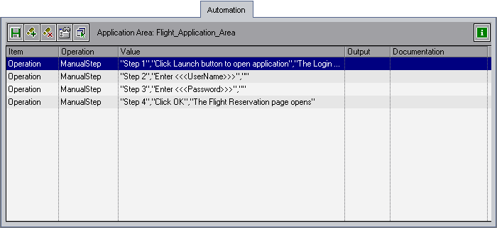
You can automate the Component similarly how you automate in the QTP using keyword view. After automating the Component steps will look like as follow

Scripted Component
Navigate to the automation tab. It will display the Launch button to launch the QTP.

Click on the Launch button (QTP should be installed in the same machine), it will open the QTP and displays a pop up asking us to associate an application area to the Component.

Once the application area is associated to the Component all the resources is available to the Component, using which you can script the Component.
Step 3) Developing the BPTs
BPT’s can be automated or manual test. BPT’s consisting of the manual Business Components can be called as the Manual BPTs. BPTs created with the automated Components are called automated BPTs.
To create either manual or automated BPTs you have to use the Test Plan module in the QC.
Click on the test plan module icon in the left side pane

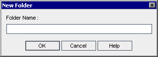
Create a folder in which you want to create Business process tests by clicking on the add folder icon.

Enter the Folder name and click on ok button
Click on the ‘Create New Test’ Icon.

Select the Test Type as ‘Business-Process’ and enter the some meaningful name to BPT.

It is displayed as follow

Select the ‘Test Script’ tab -> and select the ‘Select Component’ sub tab
It will displays the Component module tree with all the Component information at the right side

Drag and drop the Components in the logical order to form the Business scenario. You can also select the Component and use the arrow symbol instead of drag and drop as youll. Sample BPT is shown below after arranging the Components below

Even you can request for the new Component if it is not available in the Component tree from Test plan module itself by clicking the ‘New Component Request’.
Once Components are arranged in the test scripts editor pane it is displayed as five column structure:
- Component/Flow: Will display the Component along with snapshot image if it contains.
- Status: Status of the Component, it can be any one of the status which you discussed earlier.
- Input: If you have input parameters it is displayed in this column.
- Output: If you have output parameters it is displayed in this column.
-
On Failure: It will display drop down in which you can select what you would like to do the BPT execution on failure of the Component. You can select either continue or exit BPT.


Configuring Input Parameters
To configure the input parameter for any Component you need click on the input parameters link in the input column for the particular Component or you can also right click on the Component and select input parameter values -> iterations.

Once you click on the input parameter link, the Component iterations dialogue box is opened.

You can enter all the input parameter for the Component. If you want to run the Component multiple times you can add multiple iterations by clicking ‘Add Iterations’ and entering the data.
If you want to delete any iteration, first select the iteration and click on the ‘Delete Iteration’ the selected iteration is removed.
If you want to run only selected iterations you can use the ‘Select Iterations’ and you can range of iterations which you want run as shown below.

Even you can also import input parameters from external comma separated file and you can export the list parameters you used for a particular Component using import and export options.
When you click on the import option it will show File dialogue box to allow us to select the required file as shown below.

Once you selected the Map parameter dialog box will displayed in which you need to map the Column headings in the file to parameters in the Component. You have to do this exercise for all the input parameters.

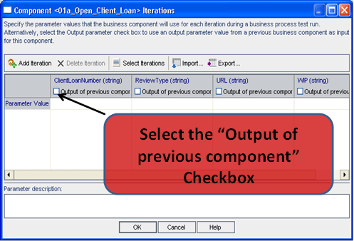
If you want to use the output parameters of the previous Components you need to click on the output check box under parameter column name.
Output parameter list window is displayed with a list of all output parameters of the previous Components. You can select the desired output parameter from that and click on ok button.

Grouping/Un-Grouping Components
Sometimes if you want to group the Components in BPT to run them together multiple times you need to group them together. First, select the Components which you want to group them and click on the Group Components image or select the Components Right-click, and select Grouping > Group Components.
![]()
After grouping Components, it will look like as below. If you want to ungroup the Components, select the group and click ungroup Components icon.

Adding Parameters/Iterations to Grouped components
It is similar to how you enter the data for a parameter for single Component, but the only difference is that when you click on any input parameter link of grouped Component it will displays the input parameter of all the Components together.
BPT Status
Like Component have a different status, BPTs also will have the different status based on the BPT creation and its progress. A BPT can be any one of the following status at any given point of time.
![]() 6 Under Development
6 Under Development
![]() 7 Ready
7 Ready
![]() 8 Maintenance
8 Maintenance
![]() 9 Error
9 Error
The BPTs status can be determined by the status of its Components. BPT status is determined by the most severe state of all its Components.
For example, suppose you have a Business process test that contains:
- 3 Ready Components
- 1 Maintenance Component
- 2 Under Development Component
- 1 Error Component
- 1 Under Development (requested) Component
In this example, the test status is Error, because Error is the most severe status of a Business Component in the test.
Step 4) Debugging the BPT
Once the BPTs are designed you need to run the BPT to check whether the Components are arranged in the proper order and the data you passed is working properly or not. It is similar to Testing our automation script with all possible ways (positive and negative) and data to check the accuracy of the script.
In the test, plan module click the Run or Debug Test button in the Test Script toolbar.

Once click on the run button ‘Run or Debug Test’ window is displayed. In the Run window, you have two options for how you want to run our BPT.
- Normal
-
Debug


Debug Mode: When you run Component in this mode, by default it adds a breakpoint at first line of the Component, which will help us to debug the Component line by line.
Normal Mode: In this mode, it runs from start to finish without pausing and continues immediately to the next Component in the test.
You can select any one of the mode for the each of the Component depending on your requirement. If you already verified some of the Components in the same BPT or in another BPT then you can go directly for Normal mode.
Once the execution is done it will show the execution summary of the all Components of the BPT.

Step 5) Executing the BPT
Once the BPTs are developed and tested thoroughly you may need to run these BPTs as part of regression, sanity or any other testing cycle.
To Execute the BPTs you need to use the Test Lab module of QC. Navigate to Test Lab and select the Test plan folder and Test set under which you want to run these BPTs.

Select the ‘Select Tests’ option from Test Lab Grid, at the right hand side, one pane is displayed with a Test plan tree structure where all the test cases. Select the BPTs which you want to run and click on the arrow button, BPTs is added to the ‘Execution Grid’. Even you can use drag and drop feature also to select the BPTs which you want to run.
Once the BPTs are added to the execution grid, you need to click on the ‘Run’ button.
A separate ‘Automatic Runner’ window is displayed after clicking the ‘Run’ button, in which you have to mention in which machine you have to run these BPTs. The machine in which you want to run, QTP software should be available. You can run the tests in the same machine as youll.

After mentioning the machine names in ‘Run on Host’ column you need click on ‘Run All’ if you want to run all the tests in the ‘Automatic Runner’ window or select ‘Run’ if you want to run only the selected BPT.
QC will automatically connects to the mentioned machine and will execute the BPT and updates the results back to QC with Pass or Fail status.

If you double click on the particular test it will display further and detailed results of the particular test.

This tutorial is made possible with contributions of Mr. Narender Reddy Nukala