UML Notation Tutorial: UML Diagram Symbol with Examples
⚡ Smart Summary
UML Notation and diagram symbols provide a standard visual vocabulary for modeling software systems. This resource explains the three building blocks of UML—things, relationships, and diagrams—and shows the exact symbol used for each structural, behavioral, and interaction element.
What is a model?
A Model is an abstraction of something to understand it before building it. As modeling omits unimportant details, it is easier to manipulate than the original entity. A model means organizing something with a particular purpose.
A model is a simplification of reality.
A model may provide:
- Blueprint of system
- Organization of the system
- Dynamic of the system
UML Building Blocks
UML stands for unified modeling language which revolves around various blocks to generate a single model. Building blocks are the things required to develop one full UML model diagram. It is an essential part of every UML diagram. Following are the basic building blocks of UML:
- Things
- Relationships
- Diagrams
Let us study in depth the building blocks and UML diagram symbols.
Things
A thing can be described as any real-world entity or an object. Things are divided into various categories in UML as follows,
- Structural things
- Behavioral things
- Grouping things
- Annotational things
Structural things
A structural thing is used to describe the static part of a model. It is used to represent the things that are visible to human eyes. Structural things in UML are all about the physical part of a system. It is the noun of a UML model, such as a class, object, interface, collaboration, use case, component, and a node.
Let us explain the Structural Things used in UML:
Class:
A class is used to represent various objects. It is used to define the properties and operations of an object. In UML, we can also represent an abstract class. A class whose functionalities are not defined is called an abstract class. Any UML class diagram notations are generally expressed as below UML class diagrams example,

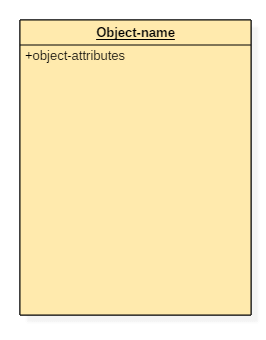
An object is an entity which is used to describe the behavior and functions of a system. The class and object have the same notations. The only difference is that an object name is always underlined in UML.
The UML notation of any object is given below.
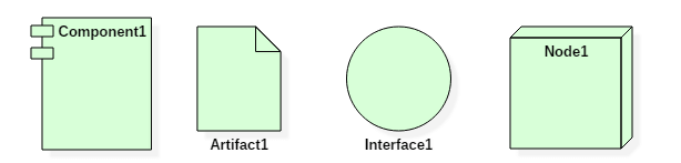
Interface:
An interface is similar to a template without implementation details. A circle notation represents it. When a class implements an interface, its functionality is also implemented.

Collaboration:
It is represented by a dotted ellipse with a name written inside it.

Use-case:
Use-cases are one of the core concepts of object-oriented modeling. They are used to represent high-level functionalities and how the user will handle the system.

Actor:
It is used inside use case diagrams. The Actor notation is used to denote an entity that interacts with the system. A user is the best example of an actor. The actor notation in UML is given below.

Component:
A component notation is used to represent a part of the system. It is denoted in UML like given below,

Node:
A node is used to describe the physical part of a system. A node can be used to represent a network, server, routers, etc. Its notation is given below.

Deployment diagram:
It represents the physical hardware on which system is installed. A deployment diagram represents the physical view of a system. It denotes the communication and interaction between various parts of the system.
A deployment diagram consists of the following notations:
- A node
- A component
- An artifact
- An interface
Behavioral things
They are the verbs of a UML model, such as interactions, activities and state machines. Behavioral things in UML are used to represent the behavior of a system.
Behavioral things consist of:
State machine:
It used to describe various states of a single component throughout the software development life cycle. It is used to capture different states of a system component.
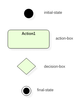
Activity diagram:
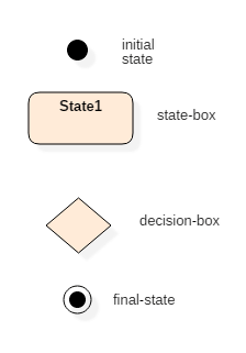
An activity diagram is used to represent various activities carried out by different components of a system. It is denoted the same as that of the state machine diagram.
Activity diagram mainly contains initial state, final state, a decision box, and an action notation.
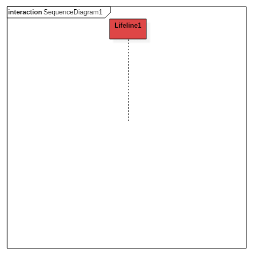
Interaction diagram:
Interaction diagrams are used to visualize the message flow between various components of a system.
- Sequence diagram: A sequence diagram shows interactions between one or more lifelines within real time.
The notation of a sequence diagram is given below,
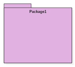
Grouping things
It is the package which is used to group semantically related modeling elements into a single cohesive unit. The package is the only grouping thing available in the UML.
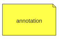
Annotational things
It is like a note, which may be written to the model to capture some vital information. It is similar to the yellow sticky note. Here is an example for annotation things in UML:
Relationships
The relationship allows you to show on a model how two or more things relate to each other. The relationship in UML will enable you to capture meaningful connections between things. It shows how each element is associated with each other and how this association describes the functionality of an application.
Relationships in UML are categorized as follows,
- Association relationship
- Dependency relationship
- Generalization relationship
- Realization relationship
Association relationship
It is a set of links that connect elements of the UML model. It also defines how many objects are taking part in that relation. It illustrates how many elements are participating in a particular interaction.
It is denoted as a dotted line with arrowheads on both sides. Both the sides contain an element which describes the relationship. A new term multiplicity is introduced that tells us how many objects of a particular element are associated.
Association relationship is denoted as follows,

Dependency relationship
In this kind of a relationship, the source element is dependent upon the target element and may be affected by changes to it. It is one of the most important notations of UML. It defines the direction of a dependency from one object to another.
It is denoted by a dotted line with an arrow at one side.
Dependency relationship is denoted as follows,

Generalization relationship
It is also called as a parent-child relationship. It is a relationship between a general thing and a more specific kind of a thing. This type of relationship is used to represent the inheritance concept.
It is denoted by a straight line with a hollow arrowhead at one side.
Generalization relationship is denoted as follows,

Realization relationship
In this, one element describes some responsibility which is not implemented and the other elements implement the functionality mentioned by the first element. Realization relationship is widely used while denoting interfaces.
It is denoted as a dotted line with a hollow arrowhead at one end.
Realization relationship is denoted as follows:

Diagrams
UML diagrams are divided into three different categories such as,
- Structural diagram
- Behavioral diagram
- Interaction diagram
Structural diagrams
Structural diagrams are used to represent a static view of a system. It represents a part of a system that makes up the structure of a system. A structural diagram shows various objects within the system.
Following are the various structural diagrams in UML:
- Class diagram
- Object diagram
- Package diagram
- Component diagram
- Deployment diagram
Behavioral diagrams
Any real-world system can be represented in either a static form or a dynamic form. A system is said to be complete if it is expressed in both the static and dynamic ways. The behavioral diagram represents the functioning of a system.
UML diagrams that deals with the static part of a system are called structural diagrams. UML diagrams that deals with the moving or dynamic parts of the system are called behavioral diagrams.
Following are the various behavioral diagrams in UML:
- Activity diagram
- Use case diagram
- State machine diagram
Interaction diagrams
Interaction diagram is nothing but a subset of behavioral diagrams. It is used to visualize the flow between various use case elements of a system. Interaction diagrams are used to show an interaction between two entities and how data flows within them.
Following are the various interaction diagrams in UML:
- Timing diagram
- Sequence diagram
- Collaboration diagram