State Machine Diagram & Statechart Diagram in UML
⚡ Smart Summary
State Machine Diagram, also called a Statechart Diagram, models the dynamic behavior of an object moving between states in response to events. This resource explains notation, state types, drawing rules, and how it differs from a flowchart.
What is a State Machine Diagram?
State Diagram are used to capture the behavior of a software system. UML State machine diagrams can be used to model the behavior of a class, a subsystem, a package, or even an entire system. It is also called a Statechart or State Transition diagram.
What is a Statechart Diagram?
Statechart diagrams provide us an efficient way to model the interactions or communication that occur within the external entities and a system. These diagrams are used to model the event-based system. A state of an object is controlled with the help of an event. Statechart diagrams are used to describe various states of an entity within the application system.
There are a total of two types of state machine diagram in UML:
1. Behavioral State Machine Diagram
- It captures the behavior of an entity present in the system.
- It is used to represent the specific implementation of an element.
- The behavior of a system can be modelled using behavioral state machine diagram in OOAD.
2. Protocol State Machine Diagram
- These diagrams are used to capture the behavior of a protocol.
- It represents how the state of protocol changes concerning the event. It also represents corresponding changes in the system.
- They do not represent the specific implementation of an element.
Why State Machine Diagram?
Statechart diagram is used to capture the dynamic aspect of a system. State machine diagrams are used to represent the behavior of an application. An object goes through various states during its lifespan. The lifespan of an object remains until the program is terminated. The object goes from multiple states depending upon the event that occurs within the object. Each state represents some unique information about the object.
Statechart diagrams are used to design interactive systems that respond to either internal or external event. Statechart diagram in UML visualizes the flow of execution from one state to another state of an object.
It represents the state of an object from the creation of an object until the object is destroyed or terminated.
The primary purpose of a statechart diagram is to model interactive systems and define each and every state of an object. Statechart diagrams are designed to capture the dynamic behavior of an application system. These diagrams are used to represent various states of a system and entities within the system.
Notation and Symbol for State Machine Diagram (Statechart Diagram)
Following are the various notations that are used throughout the state chart diagram. All these notations, when combined, make up a single diagram.

Initial state
The initial state symbol is used to indicate the beginning of a state machine diagram.
Final state
This symbol is used to indicate the end of a state machine diagram.
Decision box
It contains a condition. Depending upon the result of an evaluated guard condition, a new path is taken for program execution.
Transition
A transition is a change in one state into another state which is occurred because of some event. A transition causes a change in the state of an object.
State box
It is a specific moment in the lifespan of an object. It is defined using some condition or a statement within the classifier body. It is used to represent any static as well as dynamic situations.
It is denoted using a rectangle with round corners. The name of a state is written inside the rounded rectangle.
The name of a state can also be placed outside the rectangle. This can be done in case of composite or submachine states. One can either place the name of a state within the rectangle or outside the rectangle in a tabular box. One cannot perform both at the same time.
A state can be either active or inactive. When a state is in the working mode, it is active, as soon as it stops executing and transits into another state, the previous state becomes inactive, and the current state becomes active.
Types of State
Unified Modeling Language defines three types of states:
- Simple state
- They do not have any substate.
- Composite state
- These types of states can have one or more than one substate.
- A composite state with two or more substates is called an orthogonal state.
- Submachine state
- These states are semantically equal to the composite states.
- Unlike the composite state, we can reuse the submachine states.
How to draw a Statechart diagram?
Statechart diagrams are used to describe the various state that an object passes through. A transition between one state into another state occurs because of some triggered event. To draw a state diagram in UML, one must identify all the possible states of any particular entity.
The purpose of these UML diagrams is to represent states of a system. States plays a vital role in state transition diagrams. All the essential object, states, and the events that cause changes within the states must be analyzed first before implementing the diagram.
Following rules must be considered while drawing a state chart diagram:
- The name of a state transition must be unique.
- The name of a state must be easily understandable and describe the behavior of a state.
- If there are multiple objects, then only essential objects should be implemented.
- Proper names for each transition and an event must be given.
When to use a State Machine Diagram?
State diagrams are used to implement real-life working models and object-oriented systems in depth. These diagrams are used to compare the dynamic and static nature of a system by capturing the dynamic behavior of a system.
Statechart diagrams are used to capture the changes in various entities of the system from start to end. They are used to analyze how an event can trigger change within multiple states of a system.
State char diagrams are used:
- To model objects of a system.
- To model and implement interactive systems.
- To display events that trigger changes within the states.
Example of State Machine
Following state diagram example chart represents the user authentication process.
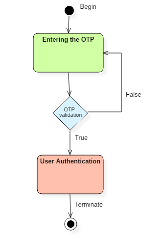
There are a total of two states, and the first state indicates that the OTP has to be entered first. After that, OTP is checked in the decision box, if it is correct, then only state transition will occur, and the user will be validated. If OTP is incorrect, then the transition will not take place, and it will again go back to the beginning state until the user enters the correct OTP as shown in the above state machine diagram example.
State Machine Diagram vs. Flowchart
Following are the key differences between Statechart Diagram and Flowchart
| State Machine Diagram | FlowChart |
|---|---|
| It represents various states of a system. | The Flowchart illustrates the program execution flow. |
| The state machine has a WAIT concept, i.e., wait for an action or an event. | The Flowchart does not deal with waiting for a concept. |
| State machines are used for a live running system. | Flowchart visualizes branching sequences of a system. |
| The state machine is a modeling diagram. | A flowchart is a sequence flow or a DFD diagram. |
| The state machine can explore various states of a system. | Flowchart deal with paths and control flow. |