What is ER Modeling? Learn with Example
⚡ Smart Summary
Entity Relationship modeling is a graphical approach to database design that represents real-world objects as entities, describes them with attributes, and captures how they connect through relationships, producing a clear blueprint before any tables are built.
What is ER Modeling?
Entity Relationship Model (ER Modeling) is a graphical approach to database design. It is a high-level data model that defines data elements and their relationship for a specified software system. An ER model is used to represent real-world objects.
An Entity is a thing or object in the real world that is distinguishable from its surrounding environment. For example, each employee of an organization is a separate entity. Following are some of the major characteristics of entities.
- An entity has a set of properties.
- Entity properties can have values.
Let’s consider our first example again. An employee of an organization is an entity. If “Peter” is a programmer (an employee) at Microsoft, he can have attributes (properties) like name, age, weight, height, etc. It is obvious that those do hold values relevant to him.
Each attribute can have values. In most cases a single attribute has one value. But it is possible for attributes to have multiple values as well. For example, Peter’s age has a single value. But his “phone numbers” property can have multiple values.
Entities can have relationships with each other. Let’s consider the simplest example. Assume that each Microsoft programmer is given a computer. It is clear that Peter’s computer is also an entity. Peter is using that computer, and the same computer is used by Peter. In other words, there is a mutual relationship between Peter and his computer.
In Entity Relationship modeling, we model entities, their attributes, and the relationships among entities.
Why Use an ER Model?
Now you may think why use ER modeling when we can simply create the database and all of its objects without ER modeling? One of the challenges faced when designing a database is the fact that designers, developers, and end-users tend to view data and its usage differently. If this situation is left unchecked, we can end up producing a database system that does not meet the requirements of the users.
Communication tools understood by all stakeholders (technical as well as non-technical users) are critical in producing database systems that meet the requirements of the users. ER models are examples of such tools.
ER diagrams also increase user productivity, as they can be easily translated into relational tables.
Enhanced Entity Relationship (EER) Model
The Enhanced Entity Relationship (EER) Model is a high-level data model that provides extensions to the original Entity Relationship (ER) model. EER models support more detailed design. EER modeling emerged as a solution for modeling highly complex databases.
EER uses UML notation. UML is the acronym for Unified Modeling Language; it is a general-purpose modeling language used when designing object-oriented systems. Entities are represented as class diagrams. Relationships are represented as associations between entities. The diagram shown below illustrates an ER diagram using the UML notation.

Case Study: ER Diagram for the “MyFlix” Video Library
Let’s now work with the MyFlix Video Library database system to help understand the concept of ER diagrams. We will use this database for all hands-on work in this tutorial.
MyFlix is a business entity that rents out movies to its members. MyFlix has been storing its records manually. The management now wants to move to a DBMS.
Let’s look at the steps to develop an EER diagram for this database:
- Identify the entities and determine the relationships that exist among them.
- Each entity, attribute, and relationship should have appropriate names that can be easily understood by non-technical people as well.
- Relationships should not be connected directly to each other. Relationships should connect entities.
- Each attribute in a given entity should have a unique name.
Entities in the “MyFlix” Library
The entities to be included in our ER diagram are:
- Members – this entity will hold member information.
- Movies – this entity will hold information regarding movies.
- Categories – this entity will hold information that places movies into different categories such as “Drama”, “Action”, and “Epic”, etc.
- Movie Rentals – this entity will hold information about movies rented out to members.
- Payments – this entity will hold information about the payments made by members.
Defining the Relationships Among Entities
Members and movies
The following holds true regarding the interactions between the two entities.
- A member can rent more than one movie in a given period.
- A movie can be rented by more than one member in a given period.
From the above scenario, we can see that the nature of the relationship is many-to-many. Relational databases do not support many-to-many relationships. We need to introduce a junction entity. This is the role that the MovieRentals entity plays. It has a one-to-many relationship with the Members table and another one-to-many relationship with the Movies table.
Movies and categories entities
The following holds true about movies and categories.
- A movie can only belong to one category, but a category can have more than one movie.
We can deduce from this that the nature of the relation between the categories and movies tables is one-to-many.
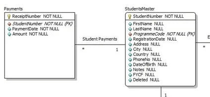
Members and payments entities
The following holds true about members and payments.
- A member can only have one account but can make a number of payments.
We can deduce from this that the nature of the relationship between the members and payments entities is one-to-many.
Create the EER Model Using MySQL Workbench
In MySQL Workbench, click the “+” button.

Double click on the Add Diagram button to open the workspace for ER diagrams.

The following window appears.
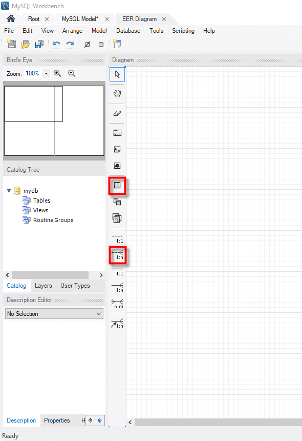
Let’s look at the two objects that we will work with.
- The table object
 allows us to create entities and define the attributes associated with the particular entity.
 - The place relationship
 button allows us to define relationships between entities.
The Members entity will have the following attributes
- Membership number
- Full names
- Gender
- Date of birth
- Physical address
- Postal address
Let’s now create the Members table
1. Drag the table object from the tools panel.
2. Drop it in the workspace area. An entity named table 1 appears.
3. Double click on it. The properties window shown below appears.

Next,
- Change table 1 to Members.
- Edit the default idtable1 to membership_number.
- Click on the next line to add the next field.
- Do the same for all the attributes identified in the Members entity.
Your properties window should now look like this.

Repeat the above steps for all the identified entities.
Your diagram workspace should now look like the one shown below.

Let’s create a relationship between Members and Movie Rentals
- Select the place relationship using existing columns tool.
- Click on membership_number in the Members table.
- Click on reference_number in the MovieRentals table.

Repeat the above steps for other relationships. Your ER diagram should now look like this –
